For DIRECTLY Operating Single Phase Pump Motors up to 2 HP
Where the Pump Motor is being operated with the help of a switch or an MCB ( ONLY for those Single Phase PUMP MOTORS which need only RUN Capacitors for their operation, like Mono-block Pump Motors )
For 1 HP Pump Motors
- With AUTO-OFF-BYPASS Switch
- In AUTO Mode , the Motor switches ON automatically when the Water Tank goes empty and switches OFF when the Water Tank fills up .
- In BYPASS mode , the Water Level Controller gets bypassed and the user can operate the Pump Motor as and when required , with the help of Switch or MCB.
- Equipped with the following LED Indications
- TANK FULL : Green
- TANK EMPTY : Red
- MOTOR ON : Red
- Suitable for both Stainless Steel/Carbon Sensors & Float Switches ( The user can install Sensors of his choice )
- Placement of Stainless Steel / Carbon SENSORS in the Water Tank and the ADJUSTMENT of KNOB of the Water Level Controller ( Without KNOB ADJUSTMENT , the Water Level Controller will NOT function properly .)
( Refer U-TUBE Video ) - Placement of FLOAT SWITCH in the Water Tank and the ADJUSTMENT of KNOB of the Water Level Controller (Without KNOB ADJUSTMENT , the Water Level Controller will NOT function properly )
Refer U-TUBE Video
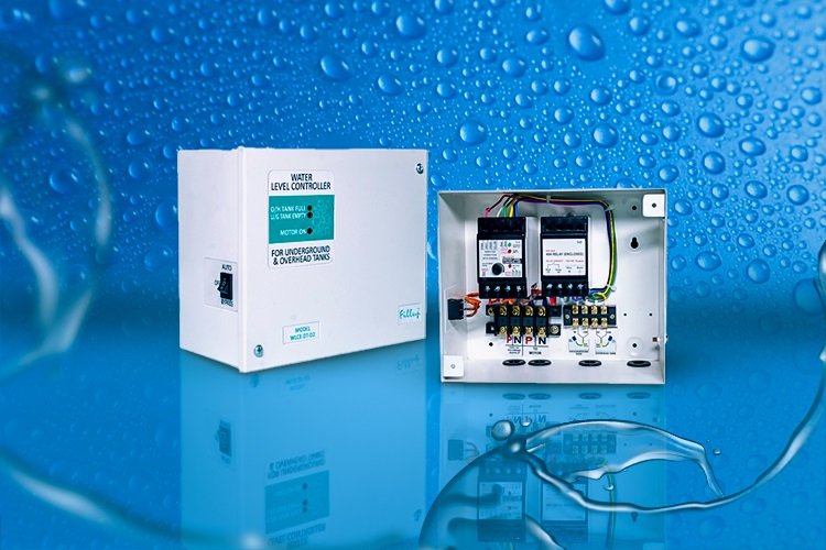
WLC-OH-D3
Features
- 30A Relay in a separate housing
- 15A Terminal Blocks for Incoming and Outgoing Supply for the Pump Motor
- With Auto-OFF-Bypass Switch
- With MOTOR ON , TANK EMPTY and TANK FULL indications
WLCE-OH-D3
Features
- 30A Relay in a separate housing
- 15A Terminal Blocks for Incoming and Outgoing Supply for the Pump Motor
- With Auto-OFF-Bypass Switch
- With MOTOR ON , TANK EMPTY and TANK FULL indications
Installation
Knob Setting Instructions
Electrical Connection Diagram
Guide for Making Connections
GA Drawing
Installation
Knob Setting Instructions
Lorem ipsum dolor sit amet, consectetur adipiscing elit. Ut elit tellus, luctus nec ullamcorper mattis, pulvinar dapibus leo.
Electrical Connection Diagram
Lorem ipsum dolor sit amet, consectetur adipiscing elit. Ut elit tellus, luctus nec ullamcorper mattis, pulvinar dapibus leo.
Guide for Making Connections
Lorem ipsum dolor sit amet, consectetur adipiscing elit. Ut elit tellus, luctus nec ullamcorper mattis, pulvinar dapibus leo.
GA Drawing
Lorem ipsum dolor sit amet, consectetur adipiscing elit. Ut elit tellus, luctus nec ullamcorper mattis, pulvinar dapibus leo.
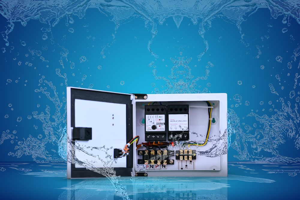
For 2 HP Pump Motors
WLC-OH-D2
Features
- 40A Relay in a separate housing
- 30A Terminal Blocks for Incoming and Outgoing Supply for the Pump Motor
- With Auto-OFF-Bypass Switch
- With MOTOR ON , TANK EMPTY and TANK FULL indications
WLCE-OH-D2
Features
- 40A Relay in a separate housing
- 30A Terminal Blocks for Incoming and Outgoing Supply for the Pump Motor
- With Auto-OFF-Bypass Switch
- With MOTOR ON , TANK EMPTY and TANK FULL indications
Installation
Knob Setting Instructions
Electrical Connection Diagram
Guide for Making Connections
GA Drawing
Installation
Lorem ipsum dolor sit amet, consectetur adipiscing elit. Ut elit tellus, luctus nec ullamcorper mattis, pulvinar dapibus leo.
Knob Setting Instructions
Lorem ipsum dolor sit amet, consectetur adipiscing elit. Ut elit tellus, luctus nec ullamcorper mattis, pulvinar dapibus leo.
Electrical Connection Diagram
Lorem ipsum dolor sit amet, consectetur adipiscing elit. Ut elit tellus, luctus nec ullamcorper mattis, pulvinar dapibus leo.
Guide for Making Connections
Lorem ipsum dolor sit amet, consectetur adipiscing elit. Ut elit tellus, luctus nec ullamcorper mattis, pulvinar dapibus leo.
GA Drawing
Lorem ipsum dolor sit amet, consectetur adipiscing elit. Ut elit tellus, luctus nec ullamcorper mattis, pulvinar dapibus leo.