WLC for Connection with Single Phase Motor Starters
For Connection with Single Phase Motor STARTERS having only RUN Capacitors up to 2 HP
- Suitable for Single Phase Motors of all HP ratings [When the Contactor in the Motor Starter has a separate HOLD-ON Contact (Auxiliary Contact)]
- Suitable for Single Phase Motors of 2 HP rating (maximum) [When there is no separate HOLD-ON Contact (Auxiliary Contact) of the Contactor. Power Contact of the Contactor itself, is used as a HOLD-ON Contact]
- For operating SOLENOID Valves
WLC-OH-SP1
Features
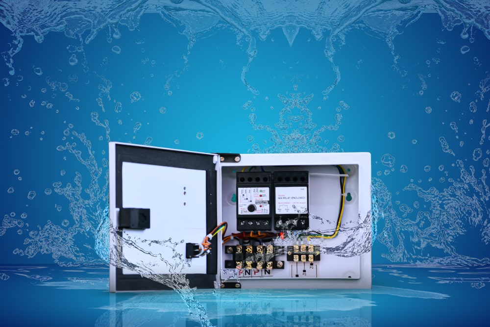
- WLC with 10A Relay
- 15A Terminal Blocks both for Supply & Sensor connections
- With Auto-Manual-Bypass Switch
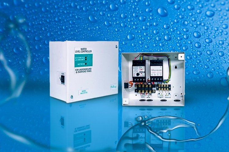
- With TANK FULL (Green), TANK EMPTY (Red) & MOTOR ON (Red) Indications
WLCE-OH-SP1
Features
- WLC with 10A Relay
- 15A Terminal Blocks both for Supply & Sensor connections
- With Auto-Manual-Bypass Switch
- With TANK FULL (Green), TANK EMPTY (Red) & MOTOR ON (Red) Indications
Installation
Knob Setting Instructions
Electrical Connection Diagram
Guide for Making Connections
GA Drawing
Installation
Knob Setting Instructions
Lorem ipsum dolor sit amet, consectetur adipiscing elit. Ut elit tellus, luctus nec ullamcorper mattis, pulvinar dapibus leo.
Electrical Connection Diagram
Lorem ipsum dolor sit amet, consectetur adipiscing elit. Ut elit tellus, luctus nec ullamcorper mattis, pulvinar dapibus leo.
Guide for Making Connections
Lorem ipsum dolor sit amet, consectetur adipiscing elit. Ut elit tellus, luctus nec ullamcorper mattis, pulvinar dapibus leo.
GA Drawing
Lorem ipsum dolor sit amet, consectetur adipiscing elit. Ut elit tellus, luctus nec ullamcorper mattis, pulvinar dapibus leo.
For Connection with Single Phase Motor STARTERS having both START & RUN Capacitors up to 2 HP
WLC-OH-SP2
Features
- WLC with 10A Relay
- 2.5 Second Timer with 40A Relay for START Capacitor Switching
- 15A Terminal Blocks both for Supply & Sensor Connections
- With Auto-Manual-Bypass Switch
- With TANK FULL (Green), TANK EMPTY (Red) & MOTOR ON (Red) Indications
WLCE-OH-SP2
Features
- WLC with 10A Relay
- 2.5 Second Timer with 40A Relay for START Capacitor Switching
- 15A Terminal Blocks both for Supply & Sensor Connections
- With Auto-Manual-Bypass Switch
- With TANK FULL (Green), TANK EMPTY (Red) & MOTOR ON (Red) Indications
Installation
Knob Setting Instructions
Electrical Connection Diagram
Guide for Making Connections
GA Drawing
Installation
Lorem ipsum dolor sit amet, consectetur adipiscing elit. Ut elit tellus, luctus nec ullamcorper mattis, pulvinar dapibus leo.
Knob Setting Instructions
Lorem ipsum dolor sit amet, consectetur adipiscing elit. Ut elit tellus, luctus nec ullamcorper mattis, pulvinar dapibus leo.
Electrical Connection Diagram
Lorem ipsum dolor sit amet, consectetur adipiscing elit. Ut elit tellus, luctus nec ullamcorper mattis, pulvinar dapibus leo.
Guide for Making Connections
Lorem ipsum dolor sit amet, consectetur adipiscing elit. Ut elit tellus, luctus nec ullamcorper mattis, pulvinar dapibus leo.
GA Drawing
Lorem ipsum dolor sit amet, consectetur adipiscing elit. Ut elit tellus, luctus nec ullamcorper mattis, pulvinar dapibus leo.
For Connection with Single Phase Motor STARTERS having both START & RUN Capacitors up to 2 HP and when there is a separate Contactor for switching the START Capacitor
WLC-OH-SP3
Features
- WLC with 10A Relay
- 2.5 Second Timer with 10A Relay for START Capacitor switching
- 15A Terminal Blocks both for Supply & Sensor connections
- With Auto-Manual-Bypass Switch
- With TANK FULL (Green), TANK EMPTY (Red) & MOTOR ON (Red) Indications
WLCE-OH-SP3
Features
- WLC with 10A Relay
- 2.5 Second Timer with 10A Relay for START Capacitor switching
- 15A Terminal Blocks both for Supply & Sensor connections
- With Auto-Manual-Bypass Switch
- With TANK FULL (Green), TANK EMPTY (Red) & MOTOR ON (Red) Indications
Installation
Knob Setting Instructions
Electrical Connection Diagram
Guide for Making Connections
GA Drawing
Installation
Lorem ipsum dolor sit amet, consectetur adipiscing elit. Ut elit tellus, luctus nec ullamcorper mattis, pulvinar dapibus leo.
Knob Setting Instructions
Lorem ipsum dolor sit amet, consectetur adipiscing elit. Ut elit tellus, luctus nec ullamcorper mattis, pulvinar dapibus leo.
Electrical Connection Diagram
Lorem ipsum dolor sit amet, consectetur adipiscing elit. Ut elit tellus, luctus nec ullamcorper mattis, pulvinar dapibus leo.
Guide for Making Connections
Lorem ipsum dolor sit amet, consectetur adipiscing elit. Ut elit tellus, luctus nec ullamcorper mattis, pulvinar dapibus leo.
GA Drawing
Lorem ipsum dolor sit amet, consectetur adipiscing elit. Ut elit tellus, luctus nec ullamcorper mattis, pulvinar dapibus leo.